News Center
Recently, Infiwave (Chengdu) Microsystem Technology Co., Ltd. successfully developed a K-band satellite phased array flat antenna sub array test prototype, achieving a breakthrough in the engineering of dual beam satellite phased array sub arrays. The implementation of dual beam control enables terminal devices to better meet the needs of maintaining links with multiple satellites in the constellation system, enhance equipment connectivity efficiency, expand network coverage, and reduce communications delay.
The prototype of the subarray has completed darkroom calibration testing work. The subarray is designed to be circularly polarized. By calibrating and testing the vertical and horizontal polarization patterns of the subarray, a circularly polarized pattern is synthesized. By testing and calibrating the axis ratio, the design specifications were met.
Table 1 Technical Indicators of Antenna Subarray
|
1. |
Working Frequency |
17.7GHz~21.2GHz |
|
2. |
Polarization Mode |
Right-Handed Circular Polarization (Adjustable) |
|
3. |
Scanning Range |
±60° |
|
4. |
Array Size |
8 x 8 |
|
5. |
Number of Active Channels |
64 RX |
|
6. |
Number of Beams |
2 |
|
7. |
Work System |
Continuous Wave |
|
8. |
Receiving Channel Gain |
≥20dB |
|
9. |
Receive G/T Values |
≥-6.5dB/K(Normal direction) |
|
10. |
First Sidelobe (Normal) |
Azimuth angle≤-13dB(Unweighted);Pitch angle≤-13dB(Unweighted) |
|
11. |
Beam Width |
Azimuth ≤13°±0.5°;Pitch ≤13°±0.5° |
|
12. |
Axis Ratio |
≤2(0°);≤3(30°);≤6(60°) |
|
13. |
Voltage Standing Wave Ratio |
≤2 |
|
14. |
Weight |
≤85g |
|
15. |
Maximum Array Size |
60mm×60mm×6mm |
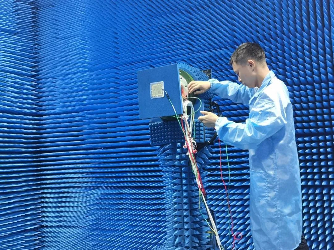
Figure 1 Prototype Darkroom Testing
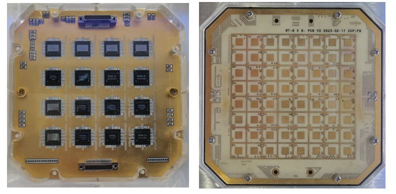
Figure 2 Physical Image of the Prototype
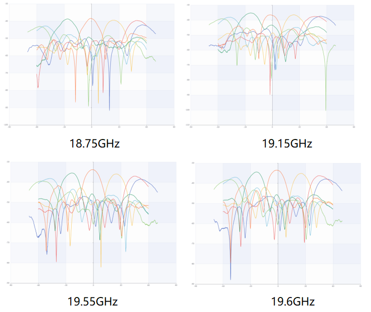
Figure 3 Circular Polarization Azimuth Scanning Direction Map
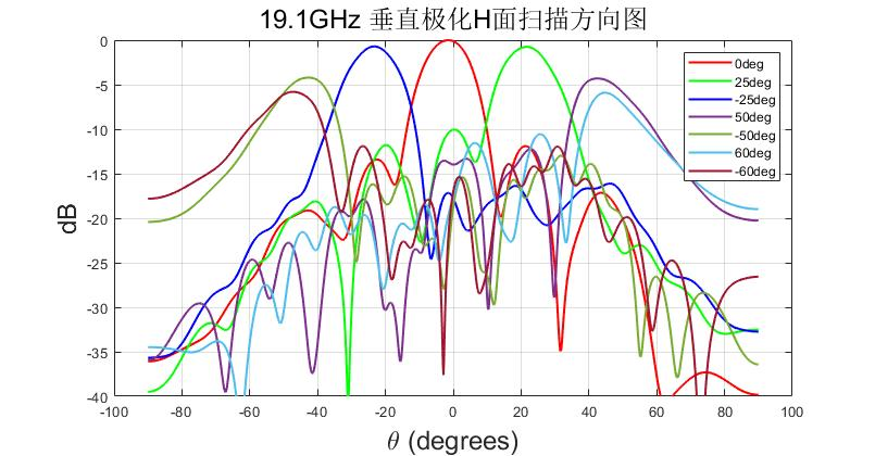
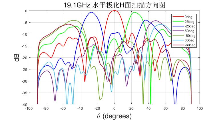
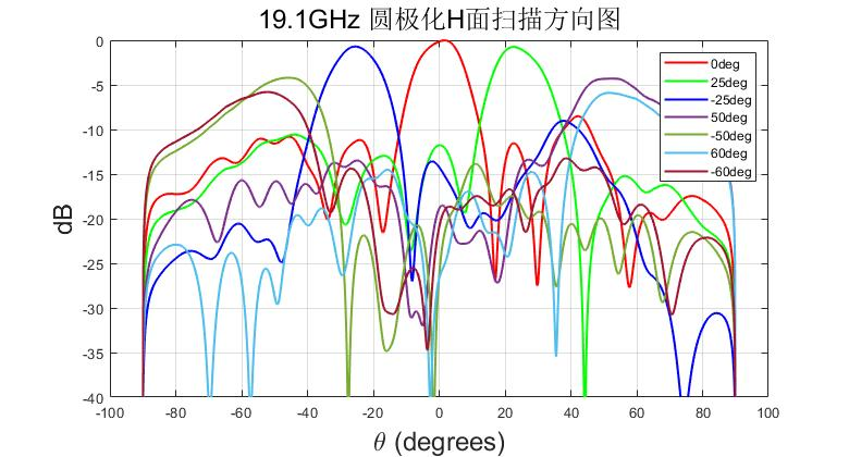
Figure 4 19.1GHz Vertical/Horizontal/Circular Polarization H-Plane Scanning Direction Map
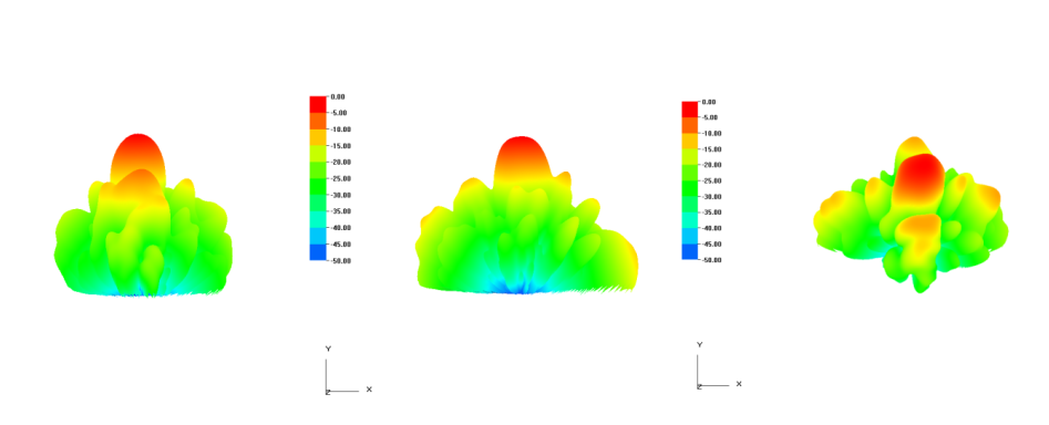
Figure 5 Vertical/Horizontal/Circular Polarization (Normal)
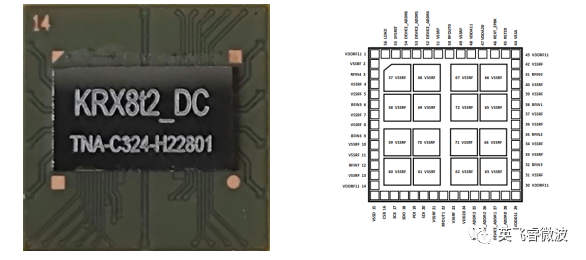
The core of this breakthrough is the use of the K-band 8-channel dual beam analog phased array receiver chip developed by Xinyang Array, a subsidiary of Ruichuang Micro Nano. This chip has achieved technological breakthroughs in multi-channel, multi beam, small-sized, low-power, and other aspects, and its performance has reached the advanced level in China, laying a solid foundation for the development of subsequent products.
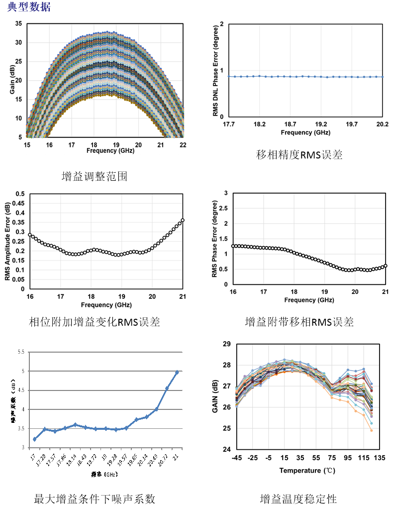
Table 2 Technical Specifications of FA8261 K-Band 8-Channel Analog Phased Array Receiver Chip
|
Number of Receiving Channels: 8 channels/linear polarization Output Beam Path: 2 beams Signal Frequency Range: 17.5~21.2GHz Temperature Sensor Accuracy: ±2.5°C Single Input P-1dB: -28dBm Single Channel Gain: 12-25.5dB adjustable Gain Temperature Stability: ±2dB@-45~125°C Stray in Band: ≤-70dBc Noise Coefficient: ≤4dB Phase Shift Range: 360° Phase Shifting Accuracy: 5.625° Phase Shift RMS Error: ≤2° Attenuation Range: 0~ 15.5dB@0.5dB Stepping RMS Attenuation Accuracy: 0.3dB Phase Consistency Between Channels: ≤5° Channel Isolation: ≥30dB Control Interface: SPI Control Response Time: 1.5ns Working Voltage: 2V Chip Power Consumption: 0.41W/dual beam working state Chip Size: 6.4mm×5.2mm |
 |
Infiwave Microsystem will continue to increase investment in the field of satellite communication, actively participate in industrial construction, promote technological innovation, and work together with more partners with an open and cooperative attitude to promote the vigorous development of the industry.